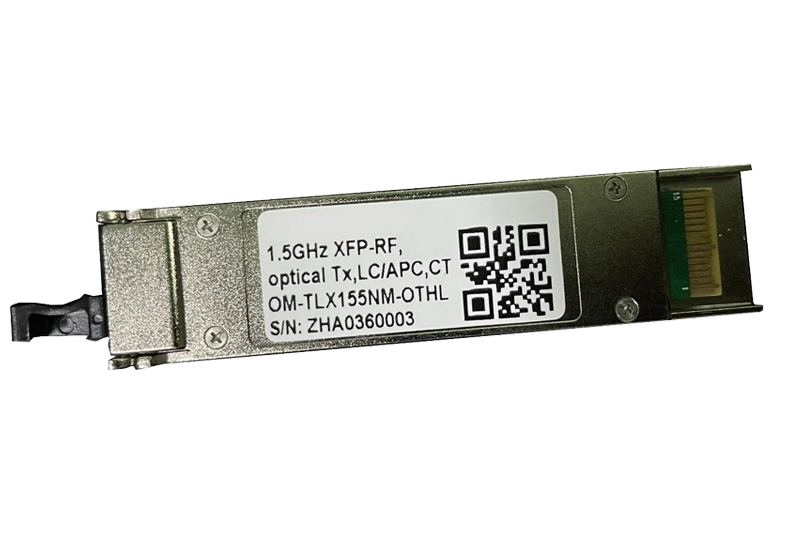
XFP-RF Optical Transmitter
This is a low power consumption, XFP form factor optical transmitter with dual optical isolators, fiber optic link up to 40KM and automatic optical power control. Ideal for antenna remote control, wireless signaling, digital QAM networks, distributed antenna systems, etc.
Model: mt04
 Dongz
Email: Sales@wxgphotonics.com
Dongz
Email: Sales@wxgphotonics.com
Features
- Low power consumption
- XFP form factor
- DOCSIS3.1 compatible
- SCTE 195 2013 compatible
- Double Optical Isolator
- LC/APC optical connection
- Fiber link up to 40km
- Excellent EMI/EMC design
- Automatic optical power control
Applications
- Antenna remoting
- Wireless signal transport
- All-Digital QAM network
- Data and video distribution
- Distributed antenna system
Absolute Maximum Ratings
| Parameter | Symbol | Condition | Min. | Max. | Unit |
|---|---|---|---|---|---|
| Operating Case Temperature | Tc | 0 | +70 | °C | |
| Storage Temperature | Tstg | -40 | +85 | °C | |
| DC Operating Voltage(+3.3V) | Vd | -- | +4 | V | |
| DC Operating Voltage(+5V) | Vd | -- | +6 | V | |
| RF Input Power | Prf | 8 | dBm | ||
| Relative Humidity | Hr | 95 | % | ||
| Pressure | Pr | 86 | 106 | kPa | |
| ESD | Human body model | Class 1B |
Typical Specification
| Parameter | Test Condition | MIN. | TYP. | MAX. | Unit | |
| Frequency Range | TLX | 50 ~ 1500 | MHz | |||
| TSX | 50 ~ 3000 | |||||
| Gain (1) | OM-TxX131NM-OT09 | 11 | 14 | -- | dB | |
| OM-TxX131NM-OT12 | 15 | 18 | ||||
| OM-TxX155NM-OTHL | 9 | 12 | ||||
| Ripple of Passband (1) | TLX | -- | ±0.8 | ±1 | dB | |
| TSX | ±1.2 | ±2 | ||||
| Output Optical Power(1) | +25℃ | OM-TxX131NM-OT09 | 8 | 9 | -- | dBm |
| OM-TxX155NM-OTHL | ||||||
| OM-TxX131NM-OT12 | 11 | 12 | -- | |||
| Optical Isolation | Double Isolator | 45 | -- | -- | dB | |
| Side Mode Suppression Ratio | 30 | 40 | -- | dB | ||
| RF Input Return Loss (1) | TLX | -- | -17 | -15 | dB | |
| TSX | -10 | -8 | ||||
| Input P-1dB (1) | OTHL@1GHz | 10 | 12 | -- | dBm | |
| OT09/OT12@1GHz | 8 | 10 | ||||
| SFDR (1) | 1GHz | 106 | 112 | -- | dB·Hz2/3 | |
| Input IP3 (1) | OTHL@1GHz | 22 | 24 | -- | dBm | |
| OT09/OT12@1 GHz | 20 | 22 | ||||
| Noise Figure (1) | OTHL/OT12@1GHz | -- | 28 | 31 | dB | |
| OT09@1GHz | 25 | 28 | ||||
| Power Consumption | +25℃ | -- | 1.4 | 2 | W | |
| Operating Voltage | +3.3, +5 | VDC | ||||
Note: (1) Test with optical receiver.The additional optical loss is 5(±1)dBand the link gain has compensated by double optical loss for OT12. (2) Typical measurement value at 25℃.Host system or chassis may degrade performance.
Alarm/Warning Threshold Information
| Address | Description | HEX | DEC | Value |
| 2 | Temp High Alarm | 55 | 85 | 85℃ |
| 3 | 0 | 0 | ||
| 4 | Temp Low Alarm | DD | 221 | -35℃ |
| 5 | 0 | 0 | ||
| 6 | Temp High Warning | 50 | 80 | 80℃ |
| 7 | 0 | 0 | ||
| 8 | Temp Low Warning | E2 | 226 | -30℃ |
| 9 | 0 | 0 | ||
| 18 | Ibias High Alarm | EA | 234 | 120mA |
| 19 | 60 | 96 | ||
| 20 | Ibias Low Alarm | 13 | 19 | 10mA |
| 21 | 88 | 136 | ||
| 22 | Ibias High Warning | C3 | 195 | 100mA |
| 23 | 50 | 80 | ||
| 24 | Ibias Low Warning | 27 | 39 | 20mA |
| 25 | 10 | 16 | ||
| 26(1) | TX_Power High Alarm | FB | 251 | 8.1dBm |
| 27(1) | F4 | 244 | ||
| 28(1) | TX_Power Low Alarm | 4F | 79 | 3.1dBm |
| 29(1) | B0 | 176 | ||
| 30(1) | TX_Power High Warning | E0 | 224 | 7.6dBm |
| 31(1) | 9C | 156 | ||
| 32(1) | TX_Power Low Warning | 59 | 89 | 3.6dBm |
| 33(1) | 74 | 116 | ||
| 42 | VCC_3.3V High Alarm | 88 | 136 | 3.50V |
| 43 | B8 | 184 | ||
| 44 | VCC_3.3V Low Alarm | 75 | 117 | 3.00V |
| 45 | 30 | 48 | ||
| 46 | VCC_3.3V High Warning | 87 | 135 | 3.46V |
| 47 | 28 | 40 | ||
| 48 | VCC_3.3V Low Warning | 7A | 122 | 3.14V |
| 49 | A8 | 168 | ||
| 50 | VCC_5V High Alarm | D2 | 210 | 5.4V |
| 51 | F0 | 240 | ||
| 52 | VCC_5V Low Alarm | B3 | 179 | 4.59V |
| 53 | 4C | 76 | ||
| 54 | VCC_5V High Warning | CA | 202 | 5.19V |
| 55 | BC | 188 | ||
| 56 | VCC_5V Low Warning | B9 | 185 | 4.74V |
| 57 | 28 | 40 |
Note :Tx Power alarm/warning information has some offset for our products. See the table below for details
TX Power Alarm/Warning Threshold Information
| Part Name | Alarm High | Warning High | Warning Low | Alarm Low | Unit |
|---|---|---|---|---|---|
| OM-TLX131NM-OT12 | 14.5 | 14 | 10 | 9.5 | dBm |
| OM-TLX131NM-OT09 | 11.5 | 11 | 7 | 6.5 | dBm |
| OM-TLX155NM-OTHL |
Connector
| Type | Connector |
|---|---|
| RF | Gold finger(100 Ω differential into XFP-RF) |
| Optical | LC/APC |
| Data/Control | Digital diagnostic functions via two-wire serial interface |
PIN Function
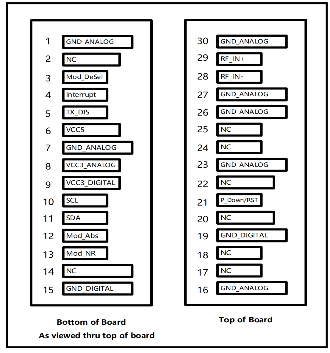
| PIN | Logic | Symbol | Name/Description | note |
| 1 | GND | Module Ground | ||
| 2 | NC | No Connection | 1 | |
| 3 | LVTTL-I | Mod_DeSel | Module De-select; When held low allows module to respond to 2-wire serial interface | |
| 4 | LVTTL-O | Interrupt | Interrupt; Indicates presence of an important condition which can be read over the 2-wire serial interface | |
| 5 | LVTTL-I | TX_DIS | Transmitter Disable; Turns off transmitter laser output | |
| 6 | VCC5 | +5V Power Supply | ||
| 7 | GND | Module Ground | ||
| 8 | VCC3 | +3.3V Power Supply | ||
| 9 | VCC3 | +3.3V Power Supply | ||
| 10 | LVTTL-I/O | SCL | 2-Wire Serial Interface Clock | |
| 11 | LVTTL-I/O | SDA | 2-Wire Serial Interface Data Line | |
| 12 | LVTTL-O | Mod_Abs | Indicates Module is not present. Grounded in the Module | |
| 13 | LVTTL-O | Mod_NR | Module Not Ready; Indicating Module Operational Fault | |
| 14 | NC | No Connection | 1 | |
| 15 | GND | Module Ground | ||
| 16 | GND | Module Ground | ||
| 17 | NC | No Connection | 1 | |
| 18 | NC | No Connection | 1 | |
| 19 | GND | Module Ground | ||
| 20 | NC | No Connection | 1 | |
| 21 | LVTTL-I | P_Down/RST | Power down; When high, requires the module to limit power consumption to 1.5W or below. 2-Wire serial interface must be functional in the low power mode. | |
| Reset; The falling edge initiates a complete reset of the module including the 2-wire serial interface, equivalent to a power cycle. | ||||
| 22 | NC | No Connection | 1 | |
| 23 | GND | Module Ground | ||
| 24 | NC | No Connection | 1 | |
| 25 | NC | No Connection | 1 | |
| 26 | GND | Module Ground | ||
| 27 | GND | Module Ground | ||
| 28 | RF_IN- | Negative RF signal input of 100 Ω differential input | ||
| 29 | RF_IN+ | Positive RF signal input of 100 Ω differential input | ||
| 30 | GND | Module Ground |
Note1: NC pin can not be connected, for example: it can not connect to GND or power supply.

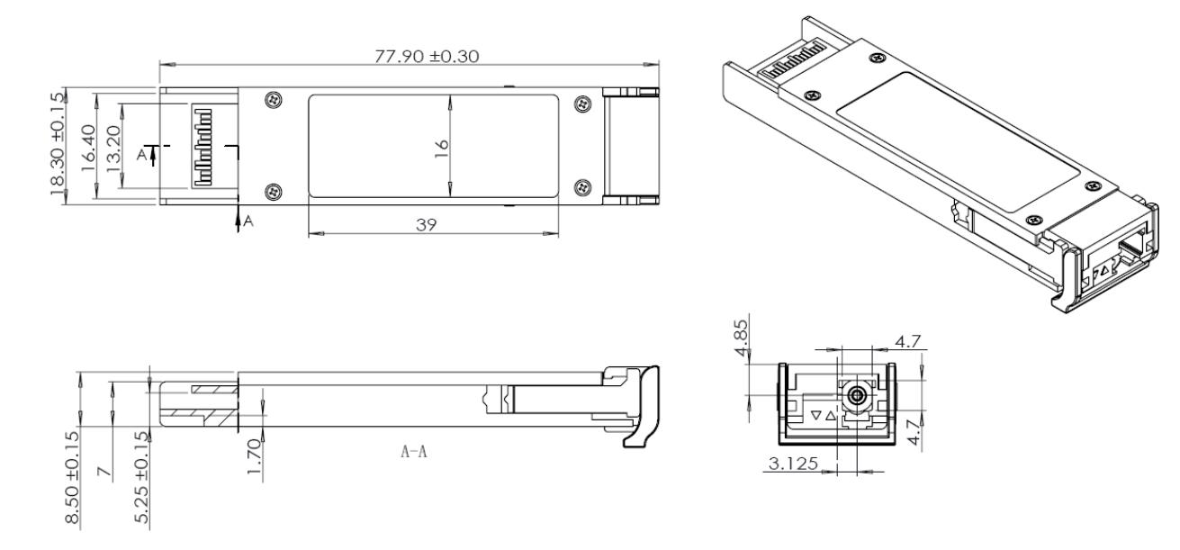
Mechanical (unit: mm)
Ordering Information
Optical Transmitter
| OM | - | T | x | X | xxx | N | M | - | O | T | xx(1) |
|---|---|---|---|---|---|---|---|---|---|---|---|
| OM: | T: | Frequency | X: | Laser | M: | Operating | Special | ||||
| Optical | Tx | Range | XFP | Wavelength | LC/APC | Temperature | HL:High Linearity | ||||
| Module | L:1.5GHz S:3GHz | 131:1310nm 155:1550nm | Pluggable | RangeT: 0 to 70℃ | 09: Output Optical Power is 9dBm 12: Output Optical Power is 12dBm |
Note1: Only HL is available for 1550nm;09 and 12 is available for 1310nm.