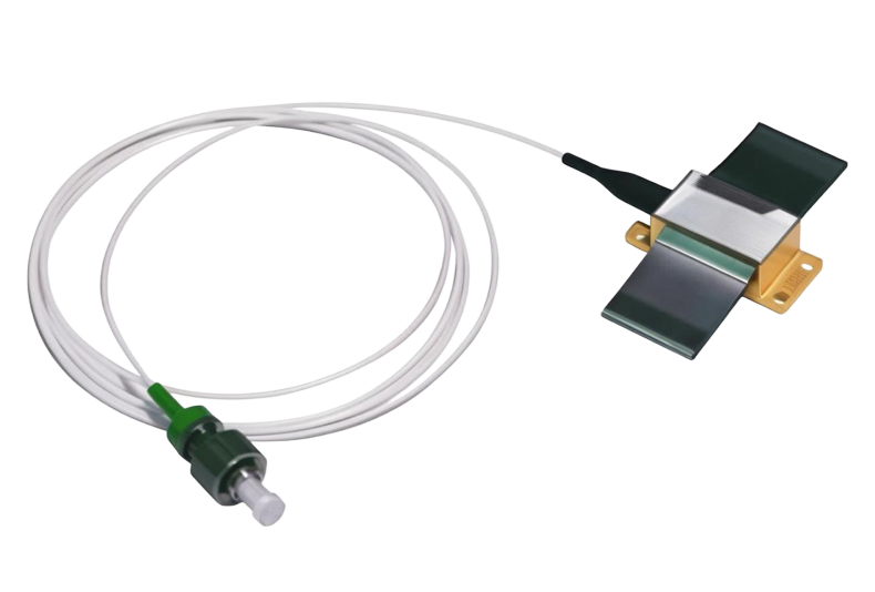
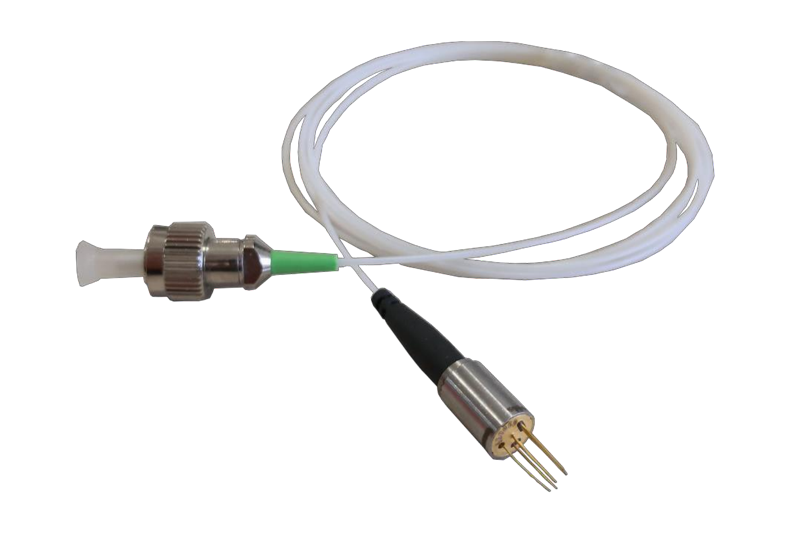
Cooled Analog Coaxial Laser Diode
This cooled analog coaxial laser diode with built-in TEC/thermistor/MPD and modulation frequency up to 18GHz can be used in fiber optic RF, RF delay line, antenna remote control, GPS transmission, broadband microwave transmission and so on.
Model: dt07
 Dongz
Email: Sales@wxgphotonics.com
Dongz
Email: Sales@wxgphotonics.com
Features
- 7 Pin coaxial package
- Single-mode fiber pigtail and FC/APC optical connector
- Built in TEC, thermistor and monitor photodiode (MPD)
- Matched to 50Ω
- High linearity DFB laser, CWDM and DWDM
- Direct modulation up to 18GHz
- With or without FPC optional
Applications
- RF over fiber
- RF delay line
- Antenna remoting
- GPS transmission
- Test and measurement
- Broadband microwave transmission
Absolute Maximum Ratings
| Parameter | Symbol | Condition | Min. | Max. | Unit |
|---|---|---|---|---|---|
| Operating Temperature | TOP | Case temperature | -40 | 70 | ˚C |
| Storage Temperature | TSTG | -40 | 85 | ˚C | |
| RF Input Power | PRF | 60 Seconds | -- | 20 | dBm |
| Laser Forward DC Current | IMAX | -- | 100 | mA | |
| Laser Reverse Voltage | VRLD | -- | 2 | V | |
| Photodiode Reverse Voltage | VRPD | -- | 20 | V | |
| TEC Voltage | VTEC | Continuous | -1.4 | 1.4 | V |
| TEC Current | ITEC | Continuous | -1.0 | 1.0 | A |
| Relative Humidity | HR | -- | 95 | % | |
| Pressure | PR | 86 | 106 | kPa | |
| ESD | -- | Human body model | Class 1A | ||
Electrical and Optical Characteristics (@25°C)
| Parameter | Symbol | Test Condition | Min | Typ. | Max | Unit |
|---|---|---|---|---|---|---|
| Center Wavelength(1) | λc | CWDM ITH +20mA | λc -3 | λc | λc +3 | nm |
| Center Wavelength(1) | λc | DWDM ITH +20mA | λc -0.2 | λc | λc +0.2 | nm |
| Optical Power | POP | IOP = ITH +20mA | 3 | 3.5 | -- | mW |
| Threshold Current | ITH | TLD =25°C | -- | 5 | 11 | mA |
| Laser Drive Current | IOP | -- | -- | 100 | mA | |
| Laser Forward Voltage | VF | I= IMAX | -- | 1.5 | 2 | V |
| Relative Intensity Noise | RIN | P=POP | -- | -- | -150 | dB/Hz |
| Side Mode Suppression | SMSR | P=POP | 30 | 40 | -- | dB |
| Optical Isolation | ISO | 30 | 35 | -- | dB | |
| MPD Current | IPD | Iop =50mA | 50 | -- | -- | μA |
| MPD Dark Current | ID | -- | -- | 100 | nA | |
| Tracking Error | TE | P=POP | -1.0 | -- | +1.0 | dB |
| TEC Voltage | VTEC | All case | -- | -- | 1.4 | V |
| TEC Current | ITEC | All case | -- | -- | 1.0 | A |
| Thermistor Resistance | RTH | T=25°C | 9900 | 10000 | 10100 | Ω |
| Thermistor β coefficient | β | 0 / 50°C | -- | 3930 | -- |
Note(1):Wavelength option refer to order information.
CWDM RF Characteristics(2)
| Parameter | Test Condition | Min | Typ. | Max | Unit | |||
| Frequency Range | LST | 0.01 ~ 3 | GHz | |||||
| LCT | 0.01 ~ 6 | |||||||
| LXT | 0.01 ~ 12 | |||||||
| LYT | 0.1 ~ 16 | |||||||
| LUT ○1 | 0.1 ~ 18 | |||||||
| LUT ○2 | 0.5 ~ 18 | |||||||
| LKT | 0.5 ~ 21 | |||||||
| Gain | -30 | -26 | -- | dB | ||||
| Amplitude Flatness | LST , 100M~3GHz | -- | ±1.2 | ±2.0 | dB | |||
| LCT , 100M~6GHz | -- | ±1.5 | ±2.2 | |||||
| LXT , 100M~12GHz | 1270nm~1370nm | -- | ±2.0 | ±2.5 | ||||
| 1550nm | -- | ±2.0 | ±3.0 | |||||
| LYT , 100M~16GHz | -- | ±2.0 | ±3.0 | |||||
| LUT ○1 , 100M~18GHz | -- | ±2.5 | ±3.0 | |||||
| LUT ○2 , 500M~18GHz | -- | ±2.0 | ±3.0 | |||||
| LKT , 500M~21GHz | -- | ±2.0 | ±3.0 | |||||
| Input Return Loss (50Ω) | LST , 100M~3GHz | -- | -15 | -10 | dB | |||
| LCT , 100M~6GHz | -- | -10 | -7 | |||||
| LXT , 100M~12GHz | -- | -10 | -5 | |||||
| LYT , 100M~16GHz | -- | -10 | -5 | |||||
| LUT ○1 , 100M~18GHz | -- | -10 | -4 | |||||
| LUT ○2 , 500M~18GHz | -- | -10 | -4 | |||||
| LKT , 500M~21GHz | -- | -10 | -3 | |||||
| Input 1 dB Compression | 1GHz | -- | 18 | -- | dBm | |||
| Spurious-free Dynamic Range | LST | 1GHz | 1270nm~1370nm | 111 | 117 | -- | dB .Hz2/3 | |
| 1530nm/1550nm | 111 | 117 | -- | |||||
| 2GHz | 1270nm~1370nm | 109 | 115 | -- | ||||
| 1530nm/1550nm | 109 | 115 | -- | |||||
| 3GHz | 1270nm~1370nm | 107 | 115 | -- | ||||
| 1530nm/1550nm | 105 | 113 | -- | |||||
| LCT | 1GHz | 1270nm~1370nm | 111 | 117 | -- | |||
| 1530nm/1550nm | 111 | 117 | -- | |||||
| 3GHz | 1270nm~1370nm | 107 | 115 | -- | ||||
| 1530nm~1550nm | 105 | 113 | -- | |||||
| 6GHz | 1270nm~1370nm | 104 | 111 | -- | ||||
| 1530nm~1550nm | 103 | 110 | -- | |||||
| LXT | 1GHz | 111 | 117 | -- | ||||
| 6GHz | 104 | 111 | -- | |||||
| 12GHz | 99 | 107 | -- | |||||
| LYT | 1GHz | 110 | 115 | -- | ||||
| 10GHz | 105 | 111 | -- | |||||
| 16GHz | 100 | 106 | -- | |||||
| LUT ○1 | 1GHz | 110 | 115 | -- | ||||
| 10GHz | 105 | 110 | -- | |||||
| 18GHz | 100 | 105 | -- | |||||
| LUT ○2 | 1GHz | 110 | 115 | -- | ||||
| 10GHz | 105 | 110 | -- | |||||
| 18GHz | 100 | 105 | -- | |||||
| LKT | 1GHz | 110 | 115 | -- | ||||
| 10GHz | 105 | 110 | -- | |||||
| 21GHz | 97 | 102 | -- | |||||
| Input Third-Order Intercept | LST | 1GHz | 30 | 34 | -- | dBm | ||
| 2GHz | 28 | 33 | -- | |||||
| 3GHz | 26 | 33 | -- | |||||
| LCT | 1GHz | 30 | 34 | -- | ||||
| 3GHz | 26 | 33 | -- | |||||
| 6GHz | 25 | 31 | -- | |||||
| LXT | 1GHz | 30 | 34 | -- | ||||
| 6GHz | 25 | 31 | -- | |||||
| 12GHz | 20 | 28 | -- | |||||
| LYT | 1GHz | 28 | 32 | -- | ||||
| 10GHz | 25 | 30 | -- | |||||
| 16GHz | 22 | 26 | -- | |||||
| LUT ○1 | 1GHz | 30 | 34 | -- | ||||
| 10GHz | 28 | 32 | -- | |||||
| 18GHz | 23 | 27 | -- | |||||
| LUT ○2 | 1GHz | 30 | 34 | -- | ||||
| 10GHz | 28 | 32 | -- | |||||
| 18GHz | 23 | 27 | -- | |||||
| LKT | 1GHz | 30 | 34 | -- | ||||
| 10GHz | 28 | 32 | -- | |||||
| 21GHz | 20 | 24 | -- | |||||
| Noise Figure | LST | 1270nm~1370nm | -- | 33 | 37 | dB | ||
| 1GHz | 1530nm/1550nm | -- | 33 | 37 | ||||
| 1270nm~1370nm | -- | 34 | 38 | |||||
| 2GHz | 1530nm/1550nm | -- | 35 | 39 | ||||
| 1270nm~1370nm | -- | 35 | 39 | |||||
| 3GHz | 1530nm/1550nm | -- | 37 | 42 | ||||
| LCT | 1270nm~1370nm | -- | 33 | 37 | ||||
| 1GHz | 1530nm/1550nm | -- | 33 | 37 | ||||
| 1270nm~1370nm | -- | 35 | 39 | |||||
| 3GHz | 1530nm/1550nm | -- | 37 | 42 | ||||
| 1270nm~1370nm | -- | 39 | 43 | |||||
| 6GHz | 1530nm/1550nm | -- | 40 | 45 | ||||
| LXT | 1GHz | -- | 33 | 37 | ||||
| 6GHz | -- | 39 | 43 | |||||
| 12GHz | -- | 41 | 45 | |||||
| LYT | 1GHz | -- | 33 | 37 | ||||
| 10GHz | -- | 37 | 42 | |||||
| 16GHz | -- | 41 | 46 | |||||
| LUT ○1 | 1GHz | -- | 35 | 39 | ||||
| 10GHz | -- | 41 | 45 | |||||
| 18GHz | -- | 43 | 47 | |||||
| LUT ○2 | 1GHz | -- | 35 | 39 | ||||
| 10GHz | -- | 41 | 45 | |||||
| 18GHz | -- | 43 | 47 | |||||
| LKT | 1GHz | -- | 35 | 39 | ||||
| 10GHz | -- | 41 | 45 | |||||
| 21GHz | -- | 45 | 49 | |||||
| Parameter | Test Condition | Min | Typ. | Max | Unit | |
| Frequency Range | LST | 0.01 ~ 3 | GHz | |||
| LCT | 0.01 ~ 6 | |||||
| LXT | 0.01 ~ 12 | |||||
| Gain | -30 | -26 | -- | dB | ||
| Amplitude Flatness | LST , 100M~3GHz | -- | ±1.5 | ±2.0 | dB | |
| LCT , 100M~6GHz | -- | ±1.8 | ±2.2 | |||
| LXT , 100M~12GHz | -- | ±2.0 | ±2.5 | |||
| Input Return Loss (50Ω) | LST , 100M~3GHz | -- | -15 | -10 | dB | |
| LCT , 100M~6GHz | -- | -10 | -7 | |||
| LXT , 100M~12GHz | -- | -10 | -5 | |||
| Input 1 dB Compression | 1GHz | -- | 18 | -- | dBm | |
| Spurious-free Dynamic Range | LST | 1GHz | 112 | 118 | -- | dB . Hz2/3 |
| 2GHz | 110 | 115 | -- | |||
| 3GHz | 108 | 113 | -- | |||
| LCT | 1GHz | 112 | 118 | -- | ||
| 3GHz | 108 | 113 | -- | |||
| 6GHz | 99 | 105 | -- | |||
| LXT | 1GHz | 109 | 115 | -- | ||
| 6GHz | 102 | 108 | -- | |||
| 12GHz | 95 | 101 | -- | |||
| LST | 1GHz | 33 | 38 | -- | dBm | |
| Input Third-Order Intercept | ||||||
| 2GHz | 31 | 35 | -- | |||
| 3GHz | 29 | 33 | -- | |||
| LCT | 1GHz | 33 | 38 | -- | ||
| 3GHz | 29 | 33 | -- | |||
| 6GHz | 22 | 27 | -- | |||
| LXT | 1GHz | 28 | 33 | -- | ||
| 6GHz | 24 | 29 | -- | |||
| 12GHz | 20 | 25 | -- | |||
| Noise Figure | LST | 1GHz | -- | 35 | 39 | dB |
| 2GHz | -- | 36 | 40 | |||
| 3GHz | -- | 37 | 41 | |||
| LCT | 1GHz | -- | 35 | 39 | ||
| 3GHz | -- | 37 | 41 | |||
| 6GHz | -- | 43 | 47 | |||
| LXT | 1GHz | -- | 34 | 38 | ||
| 6GHz | -- | 41 | 45 | |||
| 12GHz | -- | 47 | 51 | |||
Note (3) :Assembled in module testing with WXG Photodiode receiver and 1.0-meter SMF-28 fiber, for reference, no RF test data in DT07 test report.
Fiber Specification
| Parameter | Note |
|---|---|
| Fiber Type | Single-Mode |
| Connector Type | FC/APC (4) |
| Pigtail Length | 1m |
| Minimum Bend Radius | G.652.D 35mm |
Note (4) : Another optical connector available uponrequest.
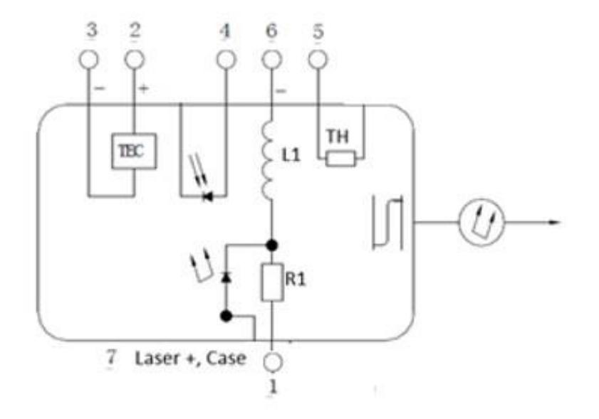
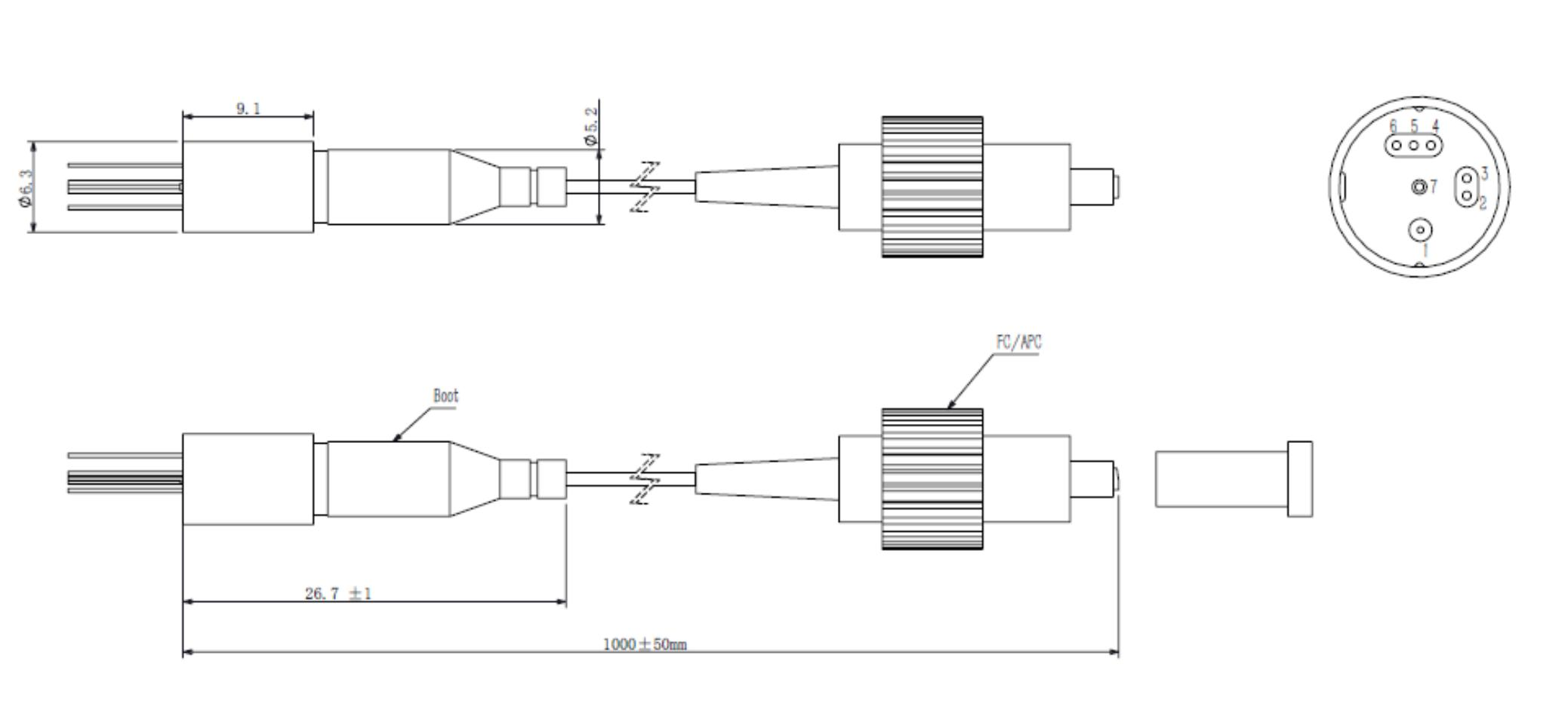
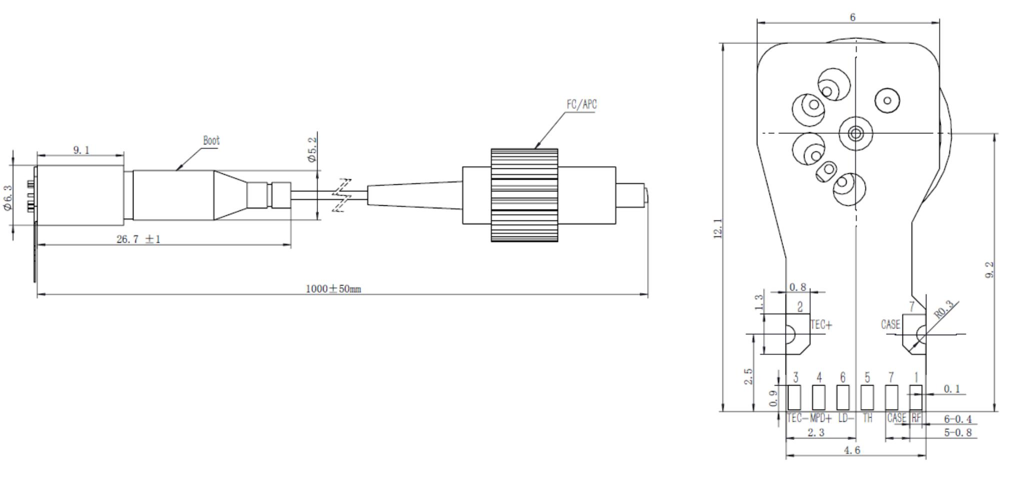
Pin Definitions
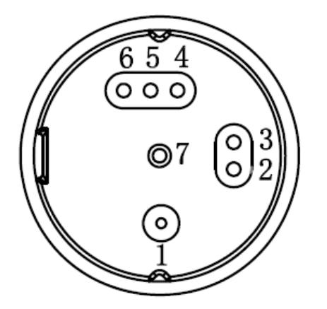
Bottom view
| Name | Note | |
|---|---|---|
| 1 | RF | RF input |
| 2 | TEC+ | Current into pin 2 cools the laser |
| 3 | TEC- | Current into pin 3 heats the laser |
| 4 | MPD+ | Monitor photodiode anode, cathode is case ground |
| 5 | THERM | One node of thermistor resistance, another node is case ground |
| 6 | BIAS_LD- | Laser cathode, negative voltage bias, anode is case ground |
| 7 | CASE | Connect to GND, MPD cathode |
Heat Dissipation Requirements
In order to ensure proper performance, heat sinking and heat removal must be provided by the user to limit maximum temperature of the device.
Mechanical Drawing (Unit: mm)
Without FPC
With FPC
Ordering Information
| OD | - | LxT | xxx | D | F | - | O | W | x0 |
|---|---|---|---|---|---|---|---|---|---|
| LST: 3.0GHz LCT: 6.0GHz LXT: 12GHz LYT: 16GHz LUT: 18GHz LKT: 21GHz | Wavelength CWDM:127:1270nm…137: 1370nm 153: 1530nm 155: 1550nm DWDM:xxC: xxis ITU channel number as below table, such as 24C is1558.17nm | OpticalConnector F: FC/APC | Operating Temperature Range W: -40 to 70℃ | 00: without FPC 30: with FPC |
| xx | Frequency(THz) | Centerwavelength(nm) | xx | Frequency(THz) | Centerwavelength(nm) |
|---|---|---|---|---|---|
| 17 | 191.7 | 1563.86 | 40 | 194.0 | 1545.32 |
| 18 | 191.8 | 1563.05 | 41 | 194.1 | 1544.53 |
| 19 | 191.9 | 1562.23 | 42 | 194.2 | 1543.73 |
| 20 | 192.0 | 1561.42 | 43 | 194.3 | 1542.94 |
| 21 | 192.1 | 1560.61 | 44 | 194.4 | 1542.14 |
| 22 | 192.2 | 1559.79 | 45 | 194.5 | 1541.35 |
| 23 | 192.3 | 1558.98 | 46 | 194.6 | 1540.56 |
| 24 | 192.4 | 1558.17 | 47 | 194.7 | 1539.77 |
| 25 | 192.5 | 1557.36 | 48 | 194.8 | 1538.98 |
| 26 | 192.6 | 1556.55 | 49 | 194.9 | 1538.19 |
| 27 | 192.7 | 1555.75 | 50 | 195.0 | 1537.40 |
| 28 | 192.8 | 1554.94 | 51 | 195.1 | 1536.61 |
| 29 | 192.9 | 1554.13 | 52 | 195.2 | 1535.82 |
| 30 | 193.0 | 1553.33 | 53 | 195.3 | 1535.04 |
| 31 | 193.1 | 1552.52 | 54 | 195.4 | 1534.25 |
| 32 | 193.2 | 1551.72 | 55 | 195.5 | 1533.47 |
| 33 | 193.3 | 1550.92 | 56 | 195.6 | 1532.68 |
| 34 | 193.4 | 1550.12 | 57 | 195.7 | 1531.90 |
| 35 | 193.5 | 1549.32 | 58 | 195.8 | 1531.12 |
| 36 | 193.6 | 1548.51 | 59 | 195.9 | 1530.33 |
| 37 | 193.7 | 1547.72 | 60 | 196.0 | 1529.55 |
| 38 | 193.8 | 1546.92 | 61 | 196.1 | 1528.77 |
| 39 | 193.9 | 1546.12 |