MT07 Series Coaxial Analog Optical Module with TEC
This is a temperature controlled coaxial analog optical transmitter module supporting C-band up to 21 GHz for antenna remote control, secure communications, fiber optic delay lines, distributed antennas, broadband, OFDM fiber optic transmission, and more!
Model: mt07
 Dongz
Email: Sales@wxgphotonics.com
Dongz
Email: Sales@wxgphotonics.com
Features
- Low noise, use coaxial optical device with TEC
- Support ITU C Band
- Wide operating frequency from 10MHz to 21GHz
- APC&ATC functions
- Flat frequency response
- High dynamic range
- Excellent EMI/EMC design, CE certification
Applications
- Antenna remoting
- Secure communication
- Fiber delay line
- Distributed antenna system
- Wideband wireless communication
- OFDM fiber transmission
Absolute Maximum Ratings
| Parameter | Symbol | Condition | Min. | Max. | Unit |
|---|---|---|---|---|---|
| Operating Temperature | Topr | Case temperature | -40 | 70 | °C |
| Storage Temperature | Tstg | -40 | 85 | °C | |
| DC Operating Voltage | Vd | -5V | -5.5 | -4.7 | V |
| +5V | 4.7 | 5.5 | |||
| RF Input Power | Prf | Continuous | -- | 20 | dBm |
| Relative Humidity | Hr | 10 | 95 | % | |
| Atmospheric Pressure | Pr | 86 | 106 | kPa | |
| ESD | Human body model | -- | Class 1A |
Typical Specification (CWDM)
| Parameter | Test Condition | Min. | Typ. | Max. | Unit | |
| Frequency Range | TSC | 0.01 ~ 3 | GHz | |||
| TCC | 0.01 ~ 6 | |||||
| TXC | 0.01 ~ 12 | |||||
| TYC | 0.1 ~ 16 | |||||
| TUC① | 0.1 ~ 18 | |||||
| TUC② | 0.5 ~ 18 | |||||
| TKC | 0.5 ~ 21 | |||||
| Optical Wavelength | λ0 is standard CWDM wavelength | Optional | nm | |||
| Optical Wavelength Range | Operating Temperature Range | λ0-3 | λ0 | λ0 +3 | nm | |
| Output Optical Power | +25℃ | -- | 9 | -- | dBm | |
| Gain (1) | Operating Temperature Range | -30 | -26 | -- | dB | |
| Gain Flatness (1) | TSC | 100MHz~3GHz | -- | ±1.2 | ±2 | dB |
| TCC | 100MHz~6GHz | -- | ±1.5 | ±2.2 | ||
| TXC | 100MHz~12GHz, 1270nm~1370nm | -- | ±2.0 | ±2.5 | ||
| 100MHz~12GHz, 1550nm | -- | ±2.0 | ±3.0 | |||
| TYC | 100MHz~16GHz | -- | ±2.0 | ±3.0 | ||
| TUC① | 100MHz~18GHz | -- | ±2.5 | ±3 | ||
| TUC② | 500MHz~18GHz | -- | ±2.0 | ±3 | ||
| TKC | 500MHz~21GHz | -- | ±2.0 | ±3 | ||
| Parameter | Test Condition | Min. | Typ. | Max. | Unit | |||
| RF Return Loss | TSC | 100MHz~3GHz | -- | -15 | -10 | dB | ||
| TCC | 100MHz~6GHz | -- | -10 | -7 | ||||
| TXC | 100MHz~12GHz | -- | -10 | -5 | ||||
| TYC | 100MHz~16GHz | -- | -10 | -5 | ||||
| TUC① | 100MHz~18GHz | -- | -10 | -4 | ||||
| TUC② | 500MHz~18GHz | -- | -10 | -4 | ||||
| TKC | 500MHz~21GHz | -10 | -3 | |||||
| Iutput P-1dB | 1GHz | -- | 18 | -- | dBm | |||
| SFDR (1) | TSC | 1GHz | 1270nm~1370nm | 111 | 117 | -- | dB·Hz2/3 | |
| 1530nm/1550nm | 111 | 117 | -- | |||||
| 2GHz | 1270nm~1370nm | 109 | 115 | -- | ||||
| 1530nm/1550nm | 109 | 115 | -- | |||||
| 3GHz | 1270nm~1370nm | 107 | 115 | -- | ||||
| 1530nm/1550nm | 105 | 113 | -- | |||||
| TCC | 1GHz | 1270nm~1370nm | 111 | 117 | -- | |||
| 1530nm/1550nm | 111 | 117 | -- | |||||
| 3GHz | 1270nm~1370nm | 107 | 115 | -- | ||||
| 1530nm/1550nm | 105 | 113 | -- | |||||
| 6GHz | 1270nm~1370nm | 104 | 111 | -- | ||||
| 1530nm/1550nm | 103 | 110 | -- | |||||
| TXC | 1GHz | 111 | 117 | -- | ||||
| 6GHz | 104 | 111 | -- | |||||
| 12GHz | 99 | 107 | -- | |||||
| TYC | 1GHz | 110 | 115 | -- | ||||
| 10GHz | 105 | 111 | -- | |||||
| 16GHz | 100 | 106 | -- | |||||
| TUC① | 1GHz | 110 | 115 | -- | ||||
| 10GHz | 105 | 110 | -- | |||||
| 18GHz | 100 | 105 | -- | |||||
| TUC② | 1GHz | 110 | 115 | -- | ||||
| 10GHz | 105 | 110 | -- | |||||
| 18GHz | 100 | 105 | -- | |||||
| TKC | 1GHz | 110 | 115 | -- | ||||
| 10GHz | 105 | 110 | -- | |||||
| 21GHz | 97 | 102 | -- | |||||
| Parameter | Test Condition | Min. | Typ. | Max. | Unit | ||
| IIP3 (1) | TSC | 1GHz | 30 | 34 | -- | dBm | |
| 2GHz | 28 | 33 | -- | ||||
| 3GHz | 26 | 33 | -- | ||||
| TCC | 1GHz | 30 | 34 | -- | |||
| 3GHz | 26 | 33 | -- | ||||
| 6GHz | 25 | 31 | -- | ||||
| TXC | 1GHz | 30 | 34 | -- | |||
| 6GHz | 25 | 31 | -- | ||||
| 12GHz | 20 | 28 | -- | ||||
| TYC | 1GHz | 28 | 32 | -- | |||
| 10GHz | 25 | 30 | -- | ||||
| 16GHz | 22 | 26 | -- | ||||
| TUC① | 1GHz | 30 | 34 | -- | |||
| 10GHz | 28 | 32 | -- | ||||
| 18GHz | 23 | 27 | -- | ||||
| TUC② | 1GHz | 30 | 34 | -- | |||
| 10GHz | 28 | 32 | -- | ||||
| 18GHz | 23 | 27 | -- | ||||
| TKC | 1GHz | 30 | 34 | -- | |||
| 10GHz | 28 | 32 | -- | ||||
| 21GHz | 20 | 24 | -- | ||||
| Noise Figure (1) | TSC | 1GHz | 1270nm~1370nm | -- | 33 | 37 | dB |
| 1530nm/1550nm | -- | 33 | 37 | ||||
| 2GHz | 1270nm~1370nm | -- | 34 | 38 | |||
| 1530nm/1550nm | -- | 35 | 39 | ||||
| 3GHz | 1270nm~1370nm | -- | 35 | 39 | |||
| 1530nm/1550nm | -- | 37 | 42 | ||||
| TCC | 1GHz | 1270nm~1370nm | -- | 33 | 37 | ||
| 1530nm/1550nm | -- | 33 | 37 | ||||
| 3GHz | 1270nm~1370nm | -- | 35 | 39 | |||
| 1530nm/1550nm | -- | 37 | 42 | ||||
| 6GHz | 1270nm~1370nm | -- | 39 | 43 | |||
| 1530nm/1550nm | -- | 40 | 45 | ||||
| TXC | 1GHz | -- | 33 | 37 | dB | ||
| 6GHz | -- | 39 | 43 | ||||
| 12GHz | -- | 41 | 45 | ||||
| TYC | 1GHz | -- | 33 | 37 | |||
| 10GHz | -- | 37 | 42 | ||||
| 16GHz | -- | 41 | 46 | ||||
| TUC① | 1GHz | 35 | 39 | ||||
| 10GHz | -- | 41 | 45 | ||||
| 18GHz | -- | 43 | 47 | ||||
| TUC② | 1GHz | 35 | 39 | ||||
| 10GHz | -- | 41 | 45 | ||||
| 18GHz | -- | 43 | 47 | ||||
| TKC | 1GHz | 35 | 39 | ||||
| 10GHz | -- | 41 | 45 | ||||
| 21GHz | -- | 45 | 49 | ||||
| Operating Current | +5V | -- | 45 | 280 | mA | ||
| -5V | -- | 75 | 100 | ||||
| Operating Voltage | +5V | 4.8 | 5 | 5.2 | VDC | ||
| -5V | -5.2 | -5 | -4.8 | ||||
| Weight | -- | 58 | 59 | g | |||
Note: ( 1 )Test with Optical Receiver and 1.0-meter SMF-28 fiber.
Typical Specification (DWDM)
| Parameter | Test Condition | Min. | Typ. | Max. | Unit | |
| Frequency Range | TSC | 0.01 ~ 3 | GHz | |||
| TCC | 0.01 ~ 6 | |||||
| TXC | 0.01 ~ 12 | |||||
| Optical Wavelength | λ0 is ITU C wavelength | Optional | nm | |||
| Optical Wavelength Range | Operating Temperature Range | λ0-0.2 | λ0 | λ0 +0.2 | nm | |
| Output Optical Power | +25℃ | -- | 9 | -- | dBm | |
| Gain (2) | Operating Temperature Range | -30 | -26 | -- | dB | |
| Gain Flatness(2) | TSC | 100MHz~3GHz | -- | ±1.5 | ±2 | dB |
| TCC | 100MHz~6GHz | -- | ±1.8 | ±2.2 | ||
| TXC | 100MHz~12GHz | -- | ±2.0 | ±2.5 | ||
| Iutput P-1dB | 1GHz | -- | 18 | -- | dBm | |
| RF Return Loss | TSC | 100MHz~3GHz | -- | -15 | -10 | dB |
| TCC | 100MHz~6GHz | -- | -10 | -7 | ||
| TXC | 100MHz~12GHz | -- | -10 | -5 | ||
| SFDR (2) | TSC | 1GHz | 112 | 118 | -- | dB·Hz2/3 |
| 2GHz | 110 | 115 | -- | |||
| 3GHz | 108 | 113 | -- | |||
| TCC | 1GHz | 112 | 118 | -- | ||
| 3GHz | 108 | 113 | -- | |||
| 6GHz | 99 | 105 | -- | |||
| TXC | 1GHz | 109 | 115 | -- | ||
| 6GHz | 102 | 108 | -- | |||
| 12GHz | 95 | 101 | -- | |||
| IIP3 (2) | TSC | 1GHz | 33 | 38 | -- | dBm |
| 2GHz | 31 | 35 | -- | |||
| 3GHz | 29 | 33 | -- | |||
| TCC | 1GHz | 33 | 38 | -- | ||
| 3GHz | 29 | 33 | -- | |||
| 6GHz | 22 | 27 | -- | |||
| TXC | 1GHz | 28 | 33 | -- | ||
| 6GHz | 24 | 29 | -- | |||
| 12GHz | 20 | 25 | -- | |||
| Noise Figure (2) | TSC | 1GHz | -- | 35 | 39 | dB |
| 2GHz | -- | 36 | 40 | |||
| 3GHz | -- | 37 | 41 | |||
| TCC | 1GHz | -- | 35 | 39 | ||
| 3GHz | -- | 37 | 41 | |||
| 6GHz | -- | 43 | 47 | |||
| TXC | 1GHz | -- | 34 | 38 | ||
| 6GHz | -- | 41 | 45 | |||
| 12GHz | -- | 47 | 51 | |||
| Operating Current | +5V | -- | 45 | 280 | mA | |
| -5V | -- | 65 | 100 | |||
| Operating Voltage | +5V | 4.8 | 5 | 5.2 | VDC | |
| -5V | -5.2 | -5 | -4.8 | |||
| Weight | -- | 58 | 59 | g | ||
Note: ( 2 )Test with Optical Receiver and 1.0-meter SMF-28 fiber.
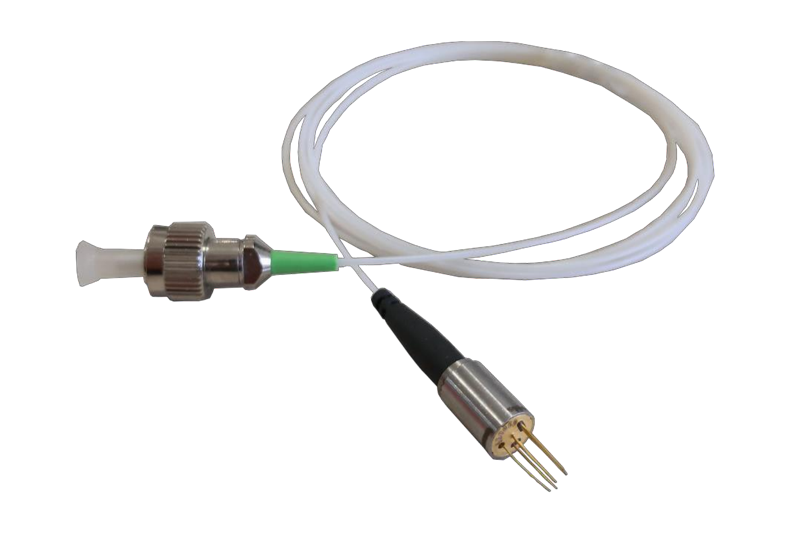
Connector
| Type | Connector |
|---|---|
| RF | SMA ( Female , 50Ω) |
| Optical | FC/APC (3) |
| Optical Fiber Type | SMF-28(Standard)(3) |
| Power | EMI Low Pass Filter, Feed Through Capacitor, Soldering Temperature Should not Exceed 300℃ and 3s |
Note: ( 3 )Other optical connector type or fiber type is also available upon request.
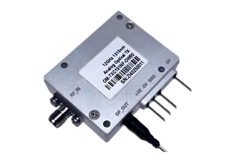
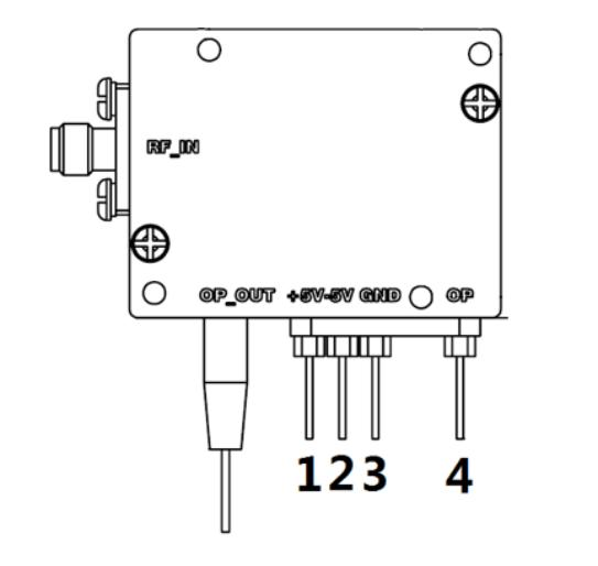
PIN Function
| PIN | Name | Direction | Note |
|---|---|---|---|
| 1 | +5V | Ⅰ | +5V DC Power |
| 2 | -5V | Ⅰ | -5V DC Power |
| 3 | GND | Ⅰ | GND |
| 4 | OP | O | Optical Power Monitor ,TTL Level ,Low Level(<0.4V)is Optical Power Low ,High Level( +5V)is Optical Power Normal. |
Heat Dissipation Requirements
In order to ensure proper performance, heat sinking and heat removal must be provided by the user to limit maximum temperature of the transmitter module.
Mechanical (unit: mm)
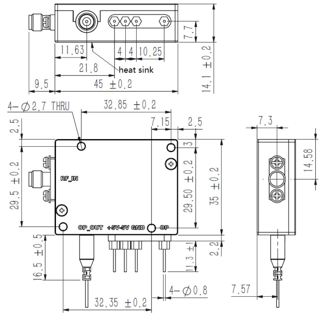
Note: The mounting holes of the module are asymmetric. Heat is dissipated from the bottom of the module. M2.5 screws are used for module installation.
Ordering Information
| OM | - | T | x | C | xxx | N | F | - | O | W | 00 |
|---|---|---|---|---|---|---|---|---|---|---|---|
| Frequency Range(4) S :3GHz C :6GHz X :12GHz | Laser Wavelength( 5 ) 127 :1270nm 129 :1290nm … 137 :1370nm 153 :1530nm 155 :1550nm xxC :xx is the ITU C band wavelength code number, see the table below | Optical Connector and Fiber TypeF :FC/APC SMF- 28 (Standard) | OperatingTemperature RangeW :-40 to 70℃ | Special 00 :Start From10MHz |
Note: ( 4 )The lower start frequency such as 9kHz is also available upon request.
( 5 )12GHz series modules are not include 1530nm wavelength.
Other optical wavelength is also available upon request.
| OM | - | T | x | C | xxx | N | F | - | O | W | 0x |
|---|---|---|---|---|---|---|---|---|---|---|---|
| Frequency Range(6) Y :16GHz U :18GHz K :21GHz | Laser Wavelength (7) 127 :1270nm 129 :1290nm … 137 :1370nm 155 :1550nm | Optical Connector and Fiber TypeF :FC/APC SMF- 28 (Standard) | OperatingTemperature RangeW :-40 to 70℃ | Special 00 :Start From 100MHz 01 :Start From 500MHz |
Note: ( 6 )The lower start frequency such as 9kHz is also available upon request.
( 7 )21GHz series modules are not include 1350nm/1370nm/1550nm wavelength. Other optical wavelength is also available upon request.
ITU C band Wavelength Code Number Table
| xx | Frequency(THz) | Center Wavelength (nm) | xx | Frequency(THz) | Center Wavelength (nm) |
|---|---|---|---|---|---|
| 17 | 191.7 | 1563.86 | 27 | 192.7 | 1555.75 |
| 18 | 191.8 | 1563.05 | 28 | 192.8 | 1554.94 |
| 19 | 191.9 | 1562.23 | 29 | 192.9 | 1554.13 |
| 20 | 192 | 1561.42 | 30 | 193 | 1553.33 |
| 21 | 192.1 | 1560.61 | 31 | 193.1 | 1552.52 |
| 22 | 192.2 | 1559.79 | 32 | 193.2 | 1551.72 |
| 23 | 192.3 | 1558.98 | 33 | 193.3 | 1550.92 |
| 24 | 192.4 | 1558.17 | 34 | 193.4 | 1550.12 |
| 25 | 192.5 | 1557.36 | 35 | 193.5 | 1549.32 |
| 26 | 192.6 | 1556.55 | 36 | 193.6 | 1548.51 |
| 37 | 193.7 | 1547.72 | 50 | 195 | 1537.4 |
| 38 | 193.8 | 1546.92 | 51 | 195.1 | 1536.61 |
| 39 | 193.9 | 1546.12 | 52 | 195.2 | 1535.82 |
| 40 | 194 | 1545.32 | 53 | 195.3 | 1535.04 |
| 41 | 194.1 | 1544.53 | 54 | 195.4 | 1534.25 |
| 42 | 194.2 | 1543.73 | 55 | 195.5 | 1533.47 |
| 43 | 194.3 | 1542.94 | 56 | 195.6 | 1532.68 |
| 44 | 194.4 | 1542.14 | 57 | 195.7 | 1531.9 |
| 45 | 194.5 | 1541.35 | 58 | 195.8 | 1531.12 |
| 46 | 194.6 | 1540.56 | 59 | 195.9 | 1530.33 |
| 47 | 194.7 | 1539.77 | 60 | 196 | 1529.55 |
| 48 | 194.8 | 1538.98 | 61 | 196.1 | 1528.77 |
| 49 | 194.9 | 1538.19 |