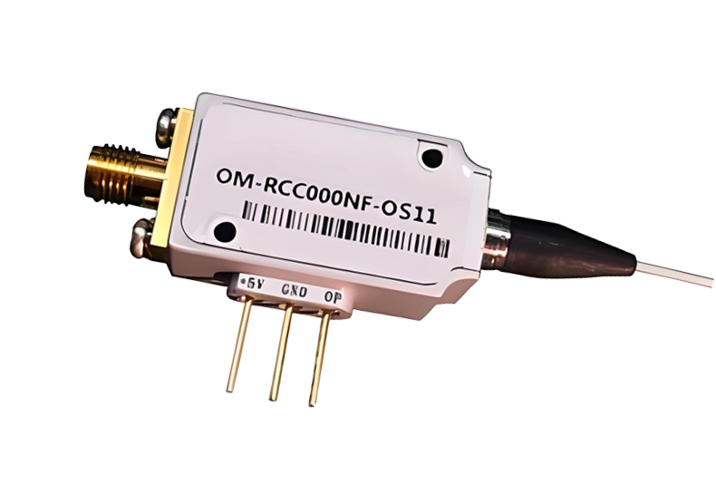
40G Analog Optical Receiver Module
This Analog Optical Receiver has low noise, long transmission distance, operating frequency up to 40GHz, integrated optical monitoring and alarm function, high dynamic range. It is used in RFOF, microcomputer communication, antenna remote control, optical delay line, microwave wireless communication and other fields
Model: mr02
 Dongz
Email: Sales@wxgphotonics.com
Dongz
Email: Sales@wxgphotonics.com
Future
- Low noise figure
- Long transmission distance up to 20km
- Flat frequency response
- Wide operating frequency range: 100MHz~40GHz
- Integrated RF LNA(Low Noise Amplifier) optional for both optical Tx and Rx
- Integrated optical monitor and alarm function both Tx and Rx
- APC(Automatic Power Control) and ATC(Automatic Temperature Control) circuits maintain small vibration of output optical power and IIP3
- High dynamic range
- Excellent EMC/EMI design
Applications
- RFoF
- Satellite communication
- Antenna remoting
- Optical Delay line
- Microwave wireless communication
- OFDM fiber transmission
Absolute Maximum Ratings
| Parameter | Symbol | Condition | Min. | Max. | Unit |
| Operating Temperature | Topr | Tx & Rx | -20 | 50 | °C |
| Storage Temperature | Tstg | -40 | 85 | °C | |
| DC Operating Voltage | Vd | Tx | 14 | 20 | V |
| Rx | 12 | 20 | |||
| RF Input Power | Prf | Tx, Without LNA | -- | 25 | dBm |
| Tx, With LNA | -- | -10 | |||
| Output Optical Power | Ps | Tx | -- | 12 | mW |
| Saturation Input Optical Power | Rx | -- | 10 | ||
| Relative Humidity | Hr | -- | 85 | % | |
| Pressure | Pr | 86 | 106 | kPa | |
| ESD | Human body model | Class 1A |
Note :Operation beyond these absolute maximum conditions may degrade device performance, lead to device failure,
shorter lifetime, and will invalidate the device warranty.
Typical Specification(1)
| Parameter | Test Condition | MIN. | TYP. | MAX. | Unit |
| Frequency Range | Without LNA | 0.1 ~ 40 | GHz | ||
| With LNA(2) | 0.3 ~ 40 | ||||
| Optical Wavelength | Tx (3) | 1550±5 | nm | ||
| Rx, optimized wavelength range (4) | 1100~1620 | ||||
| Gain (1) | Tx without LNA,Rxwithout LNA | -36 | -33 | -- | dB |
| Tx or Rx with LNA(2) | 0 | 6 | -- | ||
| Ripple of Passband (1) | 1GHz~40GHz, without LNA | -- | ±4.5 | ±5.5 | dB |
| 1GHz~40GHz, Tx or Rx with LNA(2) | -- | ±7.5 | ±9 | ||
| Output Optical Power | +25℃ | -- | 9 | -- | dBm |
| RF Return loss (1) (50 Ω) | 0.1GHz~40GHz, Tx without LNA,RFin | -- | -10 | -6 | dB |
| 0.3GHz~40GHz, Tx with LNA(2),RFin | -- | -9.5 | -5 | ||
| 0.1GHz~40GHz, Rx without LNA, RFout | -- | -9.5 | -8 | ||
| 0.3GHz~40GHz, Rx with LNA(2), RFout | -- | -9.5 | -5 | ||
| Input P-1dB(1) | Tx with LNA(2), 10GHz | -32 | -30 | -- | dBm |
| Tx without LNA, 10GHz | 9 | 11 | -- | ||
| Parameter | Test Condition | MIN. | TYP. | MAX. | Unit | |
| SFDR | Tx & Rx Without LNA | 1GHz | 105 | 112 | -- | dB·Hz2/3 |
| 10GHz | 104 | 108 | -- | |||
| 20GHz | 102 | 106 | -- | |||
| 40GHz | 100 | 102 | -- | |||
| Input IP3 | Tx & Rx Without LNA | 1GHz | 21 | 23 | -- | dBm |
| 10GHz | 20 | 22 | -- | |||
| 20GHz | 18 | 22 | -- | |||
| 40GHz | -- | 21 | -- | |||
| Noise Figure (1) | Tx without LNA | 1GHz | -- | 30 | 33 | dB |
| 10GHz | -- | 34 | 37 | |||
| 20GHz | -- | 36 | 39 | |||
| 40GHz | -- | 41 | -- | |||
| Tx with LNA(2) | 1GHz | -- | 6.5 | -- | ||
| 10GHz | -- | 7 | -- | |||
| 20GHz | -- | 8 | -- | |||
| 40GHz | -- | 9 | -- | |||
| Operating Current | Tx without LNA, +15V | -- | 240 | 350 | mA | |
| Tx with LNA(2), +15V | 600 | 730 | ||||
| Rx without LNA, +15V | -- | 20 | 50 | |||
| Rx with LNA(2), +15V | 360 | 410 | ||||
| Operating Voltage | +15V pin, Tx | 14.5 | 15 | 18 | VDC | |
| +15V pin, Rx | 14.5 | 15 | 18 | |||
Note:(1)The optical fiber connect Tx and Rx is 1-meter SMF-28 standard.
(2)The LNA operating frequency is 0.3G~40GHz and gain is 40±3.5dB and other specification
of LNA is available upon request
(3) Other wavelengths is available upon request. (4) 850nm~1650nm is useful wavelength range.
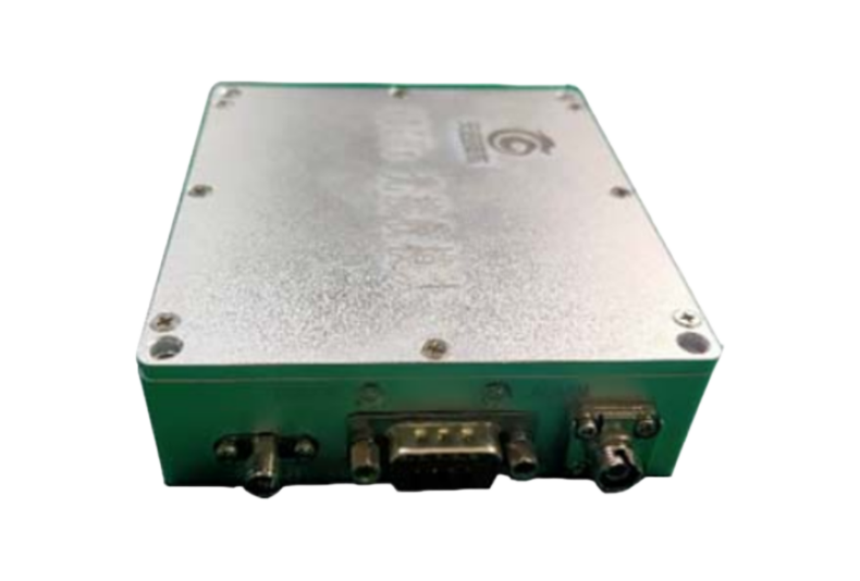
Connector
Optical Rx
| Connector | Type |
|---|---|
| RF | K type (2.92mm,50Ω), Female |
| Optical | FC/APC (1) ,Flange,the optical fiber is SMF-28(Standard) |
| Power | DB-9(Male)(2) |
Note (1): Other type optical connector available upon request.
(2) The Rx DB-9(Male) connector pin function defined as below:
Rx DB-9 PIN definition:
| PIN | Name | Direction | Note |
|---|---|---|---|
| 1 | POWER | I | Power Supply,+15V,DC |
| 2 | POWER | I | Power Supply,+15V,DC |
| 3 | GND | I/O | Ground |
| 4 | GND | I/O | Ground |
| 5 | NC | -- | No connection |
| 6 | NC | -- | No connection |
| 7 | PD_MON | O | Photodiode Receive Optical Power Monitor, DC voltage output, theoutput voltage range is 0~4V. Different voltage indicate different opticalpower received,4V indicate the max optical power(10mw usually)received and 0V indicate no optical power received. |
| 8 | NC | -- | No connection |
| 9 | NC | -- | No connection |
LED Indicators Descriptions
Optical Rx
| Name | Descriptions |
|---|---|
| POWER | Power Supply Light: when the power is turned on, the green LED is light up and always on, and the LED does not light up when the power is turned off. |
| ALARM | Photo Detector Receiving Optical power Low Alarm Light: when the Rx module is powered on and photodetector does not detect optical power or the detected optical power is less than 0dBm, the LED is light up in red; when the Rx module is powered on and the received optical power is within the normal range(>0dBm), the LED does not light up. |
Laser Safety and ESD Protection
1,The laser safety level Tx modules is ClassⅢB (5mW~500mW). When using the Tx laser, the user has to avoid to exposure to the beam.
2, The optical Tx and Rx modules have electrostatics sensitivity devices, so the user has to do a good job of ESD protection when using the modules.

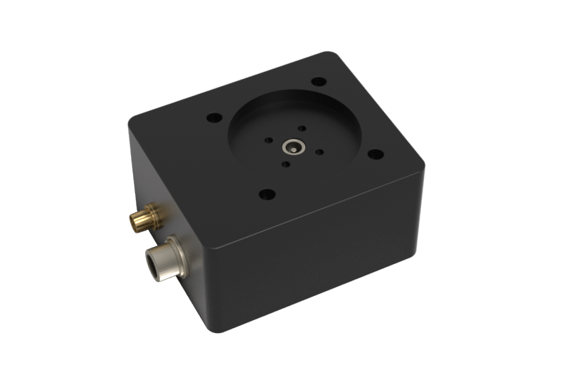
Heat Dissipation Requirements:
In order to ensure proper performance, heat sinking and heat removal must be provided by the user to limit maximum temperature of the transmitter and receiver module. The bottom of the module is the preferred heat dissipation surface.
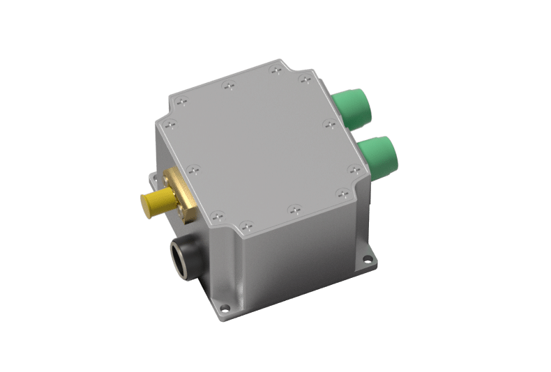
Mechanical (unit: mm)
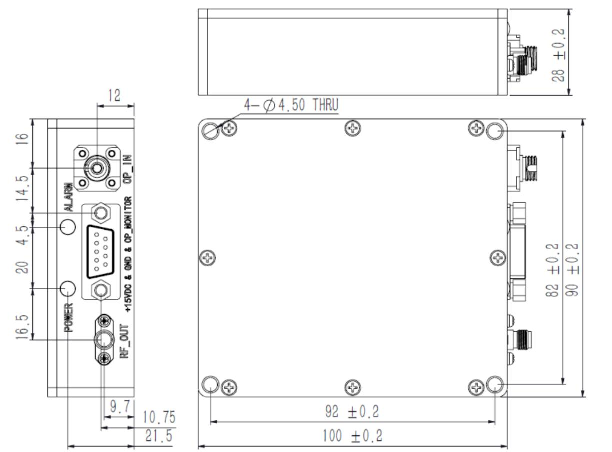
Note:The bottom of the Tx and Rx module is the preferred heat dissipation surface.
Ordering Information
Optical Receiver
| OM | - | RVC | 0 | N | F | - | O | U | xx |
|---|---|---|---|---|---|---|---|---|---|
| OM: | Frequency(1): | Wavelength: | Optical Connector and | Operating Temperature(3) | LNA(4): | ||||
| Optical Module | RVC: 100M~40GHz | 000: 1100nm~ 1620nm | Fiber(2): F: FC/APC SM | U: -20 to 50℃ | 00:without LNA | ||||
| A0: with LNA |
Note:(1) Start frequency 100MHz is available when Rx without LNA and lower start frequency such as 10MHz 、9khz or DC is available when Rx without LNA;(2) Other types of optical fiber connector are available upon request (3) Without LNA and other temperature range is available upon request (4) This LNA only supports 300M~40GHz frequency range and other specification of LNA is available upon request.