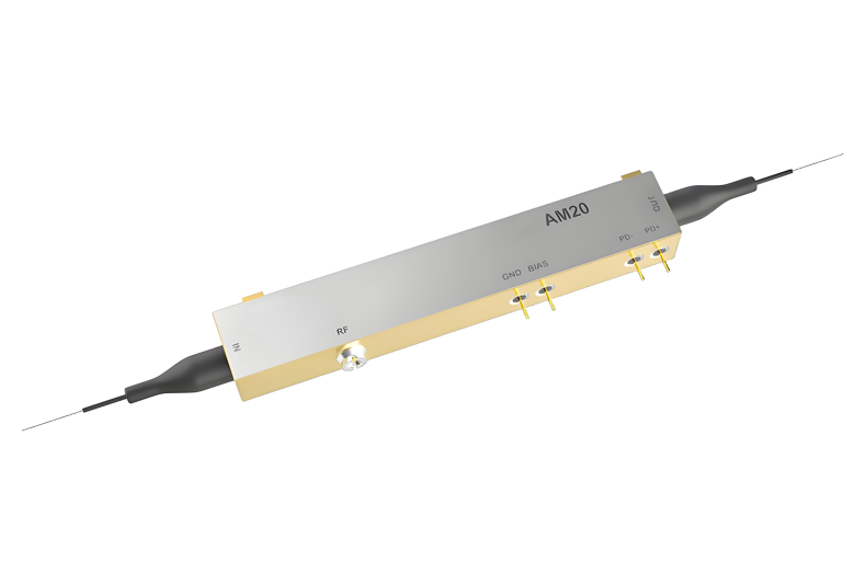
C-Band 20 GHz x 2 Extended Temperature IQ Modulator
The 40G-IQ-XT modulator design is based on a dual parallel structure of two Mach-Zehnder modulators embedded in a Mach Zehnder super-structure. Each internal modulator is designed to have EO bandwidth above 20 GHz. Monitor photodiode is provided for automatic bias control.
Model: GK40G
Applications:
RF over Fiber (ROF)
Wavelength:nm
Contact: Dongz
Email: Sales@wxgphotonics.com
Dongz
Email: Sales@wxgphotonics.com
Dongz
Email: Sales@wxgphotonics.com
Features
- Titanium-Indiffused Waveguide
- X-Cut LiNbO3
- Electro-Optic Bandwidth > 30 GHz
- Low Optical Insertion Loss
- Compliance with Telcordia GR-468-CORE
- Extended Operating Temperature at - 55 °C to + 85 °C
- Hermatically Sealed
- Excellent Linearity
Applications
- OFDM Coding
- QPSK Coding
- QAM Coding
- CS-SSB (Carrier Suppressed Single Side Band)
- FMCW LiDAR in Autonomous Driving
Performance Characteristics
Specifications
| Parameter | Conditions | Min | Typ | Max | Unit | ||||
| Optical | |||||||||
| Operating Wavelength Range | - | 1525 | - | 1570 | nm | ||||
| Insertion Loss, IL | EOL, - 5 to + 75 °C, over C-Band | - | 5 | 7 | dB | ||||
| Phase-MZI Optical Extinction Ratio | @ DC | 24 | - | - | dB | ||||
| RF-MZI Optical Extinction Ratio | @ DC | 24 | 29 | - | dB | ||||
| PER | - | 20 | - | - | dB | ||||
| Optical Return Loss, RL | Input & Output | 40 | - | - | dB | ||||
| Maximum Input Power (Optical) | CW | - | - | 100 | mW | ||||
| Electrical RF Ports | |||||||||
| RF-MZIVπ Voltage | @ 1 kHz | - | 5 | 7 | V | ||||
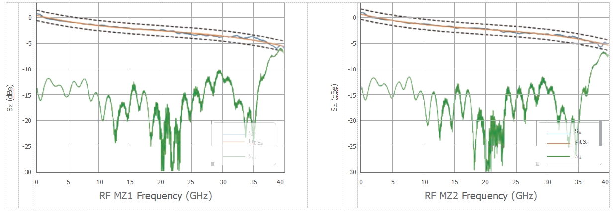
| RF-MZO - 3 dB E/O Bandwidth | wrt. 2 GHz | 20 | 23 | - | GHz | ||||
| RF-MZI S21 Flatness | 300 MHz – 20 GHz | -1 | - | 1 | dB | ||||
| Amplitude Difference Between - MZIs(Difference between two S21) | - | -1 | - | 1 | dB | ||||
| RF Delay Between RF-MZIs | - | -5 | - | 5 | ps | ||||
| RF-MZI Electrical Return Loss S11 | 40 MHz – 17 GHz | 10 | 12 | - | dB | ||||
| 17 GHz – 30 GHz | 8 | 10 | - | ||||||
Electrical Bias Ports
| RF MZI Bias Vπ Voltage | @ 1 kHz | - | 7 | 8 | V |
|---|---|---|---|---|---|
| Phase MZI Bias Vπ Voltage | @ 1 kHz | - | 7 | 8 | V |
| RF and Phase MZI Bias Vπ Voltage Variation Over Wavelength | 1550 nm | - 5 | - | 5 | % |
| Bias Port Impedance | @ DC | 1 | - | - | MΩ |
Monitor Photodiode
| Responsivity | - | 20 | - | 120 | mA/W |
| Linearity | - | -10 | - | 10 | % |
| Phase Error | PD is not inverting | -5 | - | 5 | Degree |
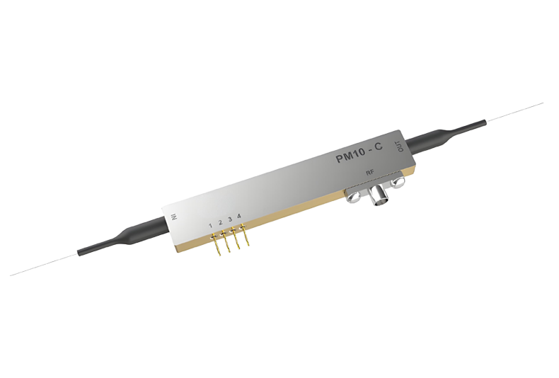
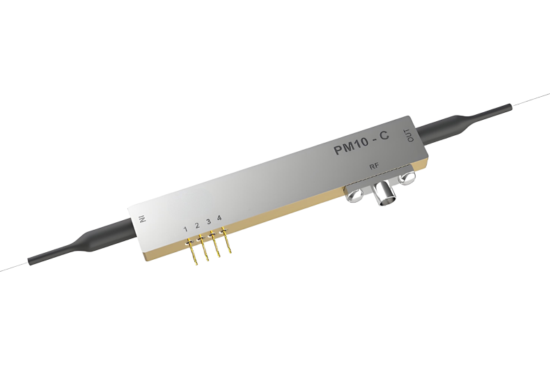
Pin-Out and Fiber Specifications
| RF Connector | SMPM male |
|---|---|
| Bias Ports | DC pins |
| Input Fiber | Polarization Maintaining Fiber, PMF - Panda (Corning/Fujikura PM15-U25D), > 1.5 m, 900 µm loose tube fiber |
| Output Fiber | Polarization Maintaining Fiber, PMF - Panda (Corning/Fujikura PM15-U25D), > 1.5 m, 900 µm loose tube fiber |
Absolute Maximum Ratings
| Parameter | Conditions | Min | Max | Unit |
|---|---|---|---|---|
| Maximum Input Power (Electrical) | RF port AC coupled | - | 10 | |
| DC Voltage at DC Port | - | - 40 | 40 | V |
| Monitor Photodiode Reverse Current | - | - | < 2 | mA |
| Monitor Photodiode Forward Current | - | - | < 10 | mA |
| Monitor Photodiode Reverse Voltage | - | - | < 15 | V |
| Operating Case Temperature | 40G-IQ-XT | - 55 | + 85 | °C |
| Maximum Top Variation Rate | 40G-IQ-XT | - | 10 | °C/min |
| Storage Temperature | 40G-IQ-XT | - 55 | + 85 | °C |
| Operating Humidity | Non-Condensing | 5 | 85 | % |
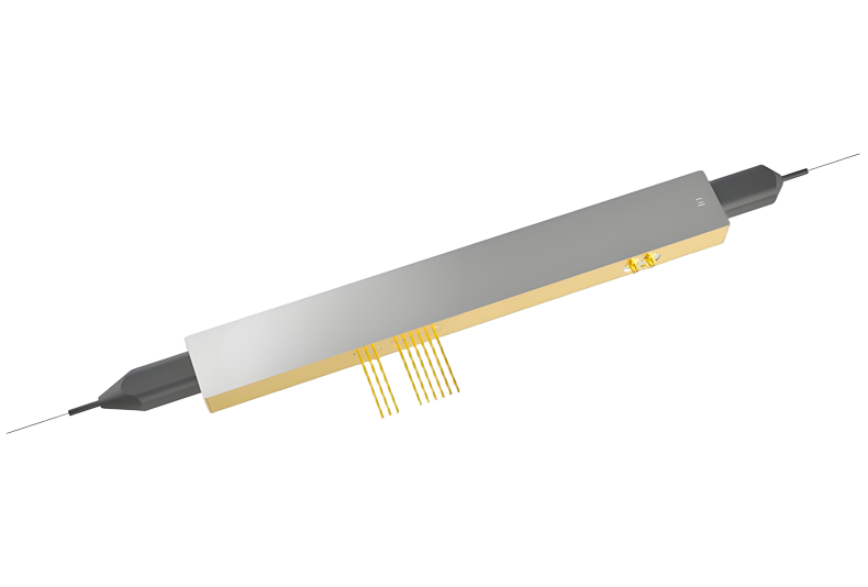
Mechanical Outline
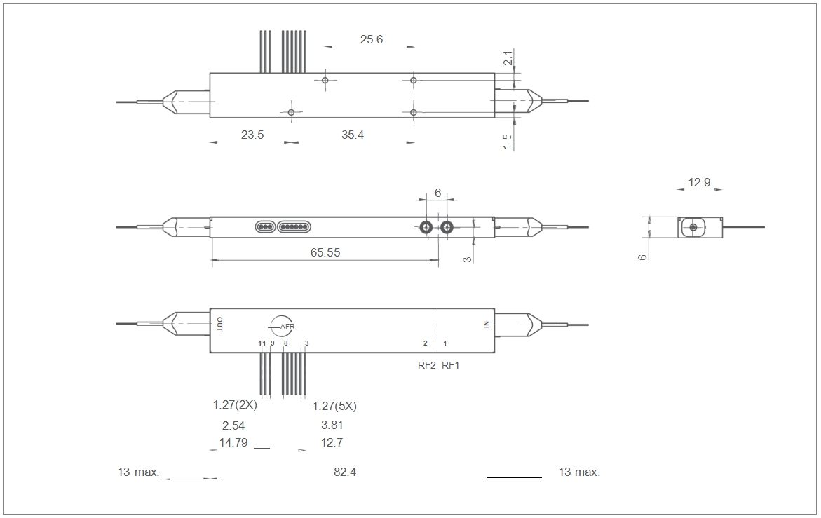
* All dimension measured in mm.
Pin-Out Information
| Pin | Name/Description | Note |
|---|---|---|
| 1 | RF. 1 | RF Input (SMPM male) |
| 2 | RF. 2 | RF Input (SMPM male) |
| 3 | BIAS 2+ | Bias wrt RF.2 +V |
| 4 | BIAS 2- | Bias wrt RF.2 -V |
| 5 | BIAS 1+ | Bias wrt RF.1 +V |
| 6 | BIAS 1- | Bias wrt RF.1 -V |
| 7 | Bias PH+ | Bias Phase +V |
| 8 | Bias PH- | Bias Phase -V |
| 9 | PD Cathode | +ve |
| 10 | PDAnode | -ve |
| 11 | GND | Ground |
Note: The pin# 3&4, 5&6, 7&8 pin pair doesn’t need to be exact as above table, but any pin pair need to be of opposite voltage.
Ordering Information
103076300008
40G-IQ-XT, C-Band 20 GHz x 2 Extended Temperature IQ Modulator (>1.4 m, 900 μm PMF/PMF loose tube fiber )
Product Inquiry
Leading manufacturer of photodetector modules and fiber optic sensing system modules